Posts

Inter-VLAN Routing: Separate Interfaces

Image
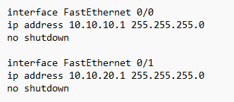
 For this protocol, I configured FE 0/0 on R1 as the default gateway for the ENG PCs and then F0/1 as the gateway for the Sales PCs.   After that, I configured SW 2 to support inter-VLAN routing using R1 as the default gateway.   I finished by verifying that ENG1 PC could ping Sales1 and Eng1 had connectivity to VLAN 20 interfaces.  

VLANS: VPT, Access and Trunk Ports

Image
  The first part of this lab required me to do a VLAN configuration for a campus network, with a Virtual Trunking Protocol, access and trunk ports, and inter-VLAN routing. The first two steps for configuring a VLAN was to verify no VLANs are active and then to verify the default switchport status between SW1 and SW2.   Next, I configured the links between switches as trunks. Here is the CLI prompts I used for SW2: After that, I configured SW1 as a VPT Server in the VTP domain Flackbox.   Then, command SW2 not to sync its VLAN database with SW1. Next, command SW 3 to learn VLAN details from SW1.   After that, I added Eng, Sales, and Native VLANs on all the switches, and then verified using the following commands:   The next step was to configure the trunk links to use VLAN 199 as the native VLAN for security reasons.   Finally, I configured the switch ports connected to the PCs with the correct VLAN configureation using the following...
OSPF--Load Balancing

Image
The lab configuration entails three network hops from R1 to reach R4, passing through R2, while there are only two hops from R5. As all the interfaces are Fast Ethernet, there would be an excessive load on R5 which could cause issues.  To solve this problem, I configured the links between R1 to R5 and then R5 to R4 at the cost of 1500.   Two hops at 1500 = total cost of 3000. Three hops at 1000 (Previously set at auto-config) = 3000.  So now the traffic should be redistributed evenly. It worked!  

OSPF Open Shortest Path First

Image
 This protocol is a link state that supports large networks.   Order of OSPF Operations: Discover neighbors Form adjacencies Share Links by Flood Link State Database Compute shortest path install best routes Respond to network changes Basic Configuration Begin by creating a loopback interface on each router.  Then enable single area OSPF oon each router.  Uses wildcard mask (inverse) of the subnet.  The loopback interfaces have the last number of the octet changed, which logically makes sense, but I kept entering this wrong on the CLI. Lots of mistakes to get to his point. I was finally able to verify that the routers formed adjacencies.  Relief when I finally got this: Next I checked the cost to see that no traffic is being routed through R5 20.0.3.2: After that, I sat the bandwidth to 100 GBPS to have a cost of 1

IGP-Interior Gateway Protocol

Image
The CCNA seems to focus primarily on OSPF, but IGP is covered as well.   No auto-summary command is added because RIP will auto summarize routes, so subnet numbers could be changed.  Setting up the protocol requires the following commands: After that, we checked to see that all networks are in the routing tables, using the show ip route.  Then we verify PC1 connects with 3 by using ping.  Next we make sure that all routers have a route to the external network, while not advertising internal routes to the service provider.   After that we create a default static route from R4 to the Internet via SP, and then make sure other routers learn via RIP how to reach Internet.  Finish by checking that each router connects.  

Review: Ethernet Frame

Image
 On my practice quizzes, I'm consistently getting the Ethernet Frame questions wrong. Time for a review!   This is from the Data-Link-Layer.  Layer 1.   Ethernet uses 48-bit MAC Address.  First 24 is the OUI (assigned by mfr) and last 24 is vendor assigned. Preamble: 64 bit header Recipient's Destination Address  6 bytes Sender Mac Address 6 bytes Type/Length 2 bytes Data Field: Payload IP Packet/ limit is 46 to 1500 bytes Pad: minim size is 64 bytes FCS: Frame Check Sequence. 4 bytes. Helps the nodes know when data has been corrupted. Devices on a network have to be able to know when errors occur. Also called "the trailer."  

Basic Connectivity Troubleshooting

Image
 Ping Responses Uses ICMP: Internet Control Message Protocol Tests two way connectivity.   Today's lab had the scenario of PC 1 not being able to reach P3.  We started by testing the connection from PC1 to P2 using the Command Prompt.   Now that the problem is verified, we use traceroute to investigate the source. Control C stopped the process. The hop stopped at 10.1.0.1, which is R3. So from here we check to see if R3 has a route to PC3, which requires us to jump back into R3's CLI.   PC3's network, 10.1.2.10 is not on the routing table, so we should manually add it! Back to the the CLI.   Now it's time to test it out the connectivity by pinging PC3 from PC1.  Success!