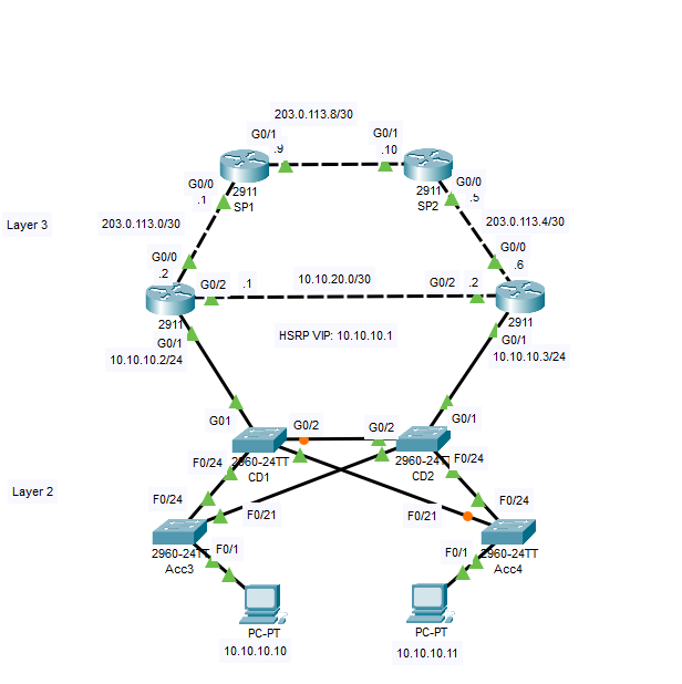
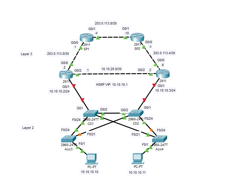
Posts

iPerf3

 Today I worked on installing and using iperf, which is a tool for measuring network performance.  I used my PC as the server and my Raspberry Pi as the client. After the tool was downloaded on both machines, the results looked like this: From the server side (PC) C:\Users\James>cd C:\iperf C:\iperf>iperf3.exe -s ----------------------------------------------------------- Server listening on 5201 (test #1) ----------------------------------------------------------- Accepted connection from 10.0.0.94, port 35190 [  5] local 10.0.0.93 port 5201 connected to 10.0.0.94 port 35194 [ ID] Interval           Transfer     Bitrate [  5]   0.00-1.01   sec  4.38 MBytes  36.3 Mbits/sec [  5]   1.01-2.01   sec  5.12 MBytes  42.9 Mbits/sec [  5]   2.01-3.01   sec  4.88 MBytes  41.0 Mbits/sec [  5]   3.01-4.00  ...

ARP--Address Resolution Protocol

 ARP is a program that helps connect an IP address to a physical address (MAC) over a Local Area Network.   An analogy/pneumonic device.   Apartment's  Real  Person The IP address on a local address is like an apartment's address in a city. It's helpful to get packages delivered, but it doesn't tell the carrier which apartment it is going. ARP helps the packet get from the apartment gate to the apartment door.  Apartment's Real Person.  

Spanning Tree Protocol Troubleshooting: Part 1

Image
  The suggested troubleshooting order begins with determining which router is the HSRP (Hot Standby Routing Protocol). I did this by going the CLI in R1 and finding the following: The preemption enabled tells me that this will be the active router–if the priority is higher than the other option, which it is.  R1 is 110, and R2 is 100.   The next Step is to ping 203.0.113.9 (SP1) from both PCs. I used the command prompt to do this. After that, I check the Layer 3 path using traceroute. The correct command is tracert not tracecert!   The layer 3 path is good, so I now know to look at layer 2–which is evident if you consider this is an STP lab. For real-world applications, I would need to check layer three first.  

HSRP Configuration

Image
I began by configuring HSRP for the 10.10.10.0/24 using the IP addresses shown in the topology above. My first step was to check to see if G0/1 has been configured on R1 & R2.   It was not on either router, so I configured them and added a virtual IP address.    After that, I checked to see which was the active router (R2). Then, I checked to see that PC2 could ping the default gateway 10.10.10.1, followed by testing upstream connectivity.   I finished this portion of the lab by checking MAC addresses on the active router, the virtual interface, and PCs.  

DHCP External Server

Image
 Looks like I lost the images of my CLI prompts and PC Command Prompts were lost when I recorded the lab work from using a router as the DHCP host.  The second part of the lab is using an external server for DHCP. This process has fewer steps.   After setting the router for DHCP earlier, I cleared the work to start over. This is the lab topology: First, I configured the network to allow the PCs to receive IP addresses from the DHCP server, and then I verified the clients received their IPs from DHCP.  The work was successful!  

DHCP

Image
 Dynamic Host Configuration Protocol is a way to automatically distribute IPs. When out working as a server engineer, I nearly always disable DHCP when setting management configurations. In the case of assigning DHCP on a small network of Cisco devices, you can use a router or an external server for the DHCP device. Here are the steps for configuring a router for DHCP.  First,  I configured the interface with the following commands: Then, I confirmed that DHCP assigned the router a public IP address.  This took longer than expected! After that, I enabled DHCP service on R1 so that it assigned iP address to the PCs in /24.  Leaving IP addressed 10.10.10.1-10 free.    After that, I made sure the clients received their IP information via DHCP.  

Inter-VLAN Routing: Router on a Stick

Image
 To configure the router on a stick protocol, I entered the following commands on router 1: After that, I configured Switch2 to support inter-VLAN routing using Router1 as the default gateway.  I then verified that ENG1 PC had connectivity with VLAN 20 interface on R1 and that it had connectivity to Sales1.